
Third party interference is the term used to describe electrical hazards from electrical transmission and distribution assets causing voltages and currents on nearby assets owned by third party utilities, these may include:
- Low Frequency Induction (LFI) onto parallel metallic objects such as fences, conveyors, pipelines, telecommunications cables
- Electrostatic Induction onto metallic objects placed (unearthed) beneath HV lines such as equipment and machinery, streetlights
- Earth Potential Rise causing step and touch voltages onto metallic objects near a faulted assets such as transmission structure or substation
Earth Faults
When a single line to ground fault occurs a significant current can flow in a faulted phase, causing voltage hazards at nearby earthing systems (touch step and transfer hazards) and induced voltages to parallel metallic services.
For a general description and introduction to earthing, read the Introduction To Electrical Earthing article.
Earth Potential Rise (EPR)
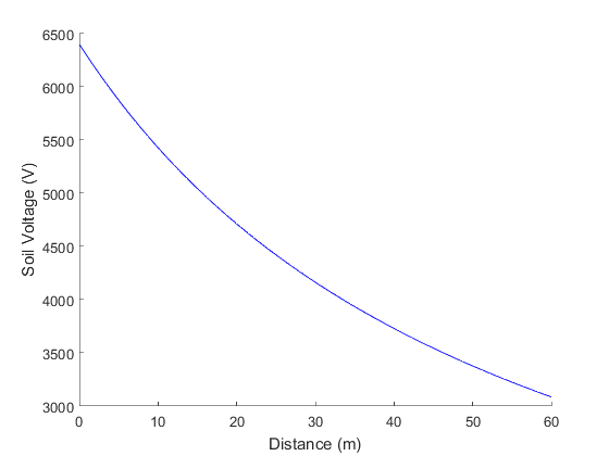
When an earth fault occurs, fault current enters the earthing system causing a voltage rise known as Earth Potential Rise, which causes the soil voltage to rise near the faulted asset. The soil voltage drops away with distance similar to the figure below.
If a person is standing on soil at a different potential to their hands, they will have a voltage difference across them which may be hazardous. This voltage difference can be exacerbated when a conductor transfers a high voltage out to where soil is low, or transfers low voltage in to where the soil is high. Fences, pipelines and long metallic objects are sources of these transfer hazards.
Earth Potential Rise
Electrostatic Induction / Capacitive Coupling
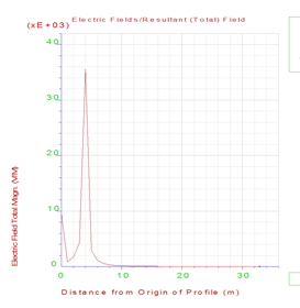
Electrostatic induction, otherwise known as capacitive coupling, occurs when a metallic object in an electric field produces a voltage proportional to the electric field strength.
Electric fields exist all around us and are produced by voltage differences, such as that between the overhead phase conductors and the earth under a high voltage line. The higher the voltage, the higher the electric field strength, which decreases non-linearly between the phase conductor and the earth.
The build up of voltage under a HV line can result in large voltages which can cause shocks when an earthed person touches it. These shocks are typically nuisance shocks, as the total energy and resultant current is often very small, but in the presence of a strong electric field, the shock may be more harmful.
For example, a streetlight under a HV line has two scenarios where a voltage may be present:
- The streetlight is unearthed and an earthed person touches it, receiving a shock
- The streetlight is earthed an insulated person touches it, receiving a shock
In scenario 1, the streetlight has charged up with energy, which is released when earthed (through a person in this case), resulting in a current flowing through the person.
In scenario 2, it is the person that has charged up with energy under the line, and the energy is released to earth through the earthed streetlight.
Electromagnetic Induction / Low Frequency Induction (LFI)
Also known as Electromagnetic Induction, Low Frequency Induction occurs in situations where a conductive object runs parallel to a current carrying conductor (such as high voltage line with a fence, pipeline, or cable running parallel for some distance).
The induction is due to the interaction of conductor inside a magnetic field producing a voltage, which seeks to drive a current to balance the net magnetic field. The magnetic field acting on the parallel conductive object is produced by the current in the phase conductor. The magnitude of induced voltage is dependent on the following:
- Current in conductor – Increased current (such as during a fault) produces larger induced voltages
- Length of parallel exposure – Longer exposure creates larger induced voltages
- Separation distances – Close distances between the phase and the parallel conductor produces larger induced voltages
- Shielding – Shielding (by overhead earth wires or screens) reduces the current and the induced voltage
When a single line to ground fault occurs, fault current flows in the phase conductor parallel to the service parallel to the feeder. Any overhead earth wire or cable screen helps to shield the service by returning some of the fault current to the source, thereby cancelling some of the resultant magnetic field acting upon the service.
This coupling factor (or its inverse the shielding factor) is a measure of the amount of current returning via the OHEW/screens, leaving the resultant current to cause voltage rise due to low frequency induction.
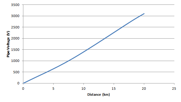
An example of the voltage induced on a parallel service (earthed at one end only) is shown in the figure below.
AS4853: Electrical Hazards on Metallic Pipeline provides a number of levels of assessment, starting with a simple comparison to a number of results produced for parallel services with a given fault level, separation distance etc.
Level 2 and 3 require comparison of induced voltages with safety targets.
To calculate the voltages induced on a parallel services, a number of software packages exist to help, however a simple equation given in AS4853 and HB102 allows a quick first pass calculation of induced voltage to be undertaken:
VLFI = ZmIlK
Where:
VLFI = Induced Voltage (V)
Zm = Mutual impedance between overhead line and parallel service (Ω/km)
I = The fault current (A)
l = The length of parallel exposure (km)
K = The shielding factor (1 – coupling factor)
The Mutual Impedance between the faulted phase and the parallel object, Zm, can be calculated using Carson’s equivalent equations, or the simple curves shown in the figure below can be used to estimate it.
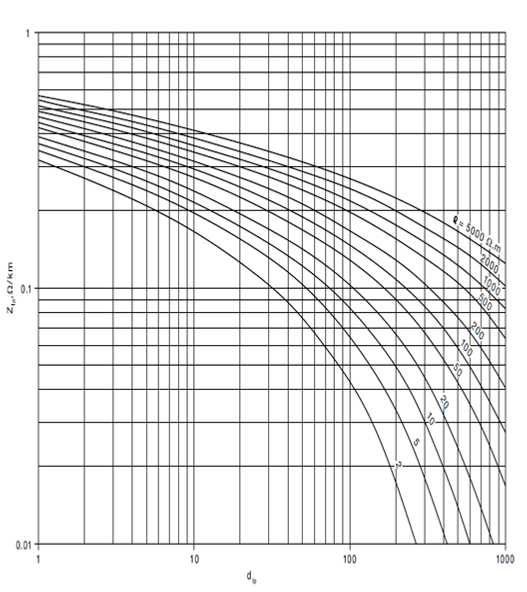
Figure: Mutual Impedance Nomogram
To obtain the shielding factor is more difficult and requires a calculation of the mutual impedance between the phase a shielding conductors and a knowledge of the circuit. For a simple an conservative first pass, we can try a shielding factor, K, or 1, meaning that there is no shielding conductors, which is applicable to 11kV and some 33kV and 66kV overhead lines.
For most assessments, Zero Sequence Earthing utilise CDEGS Hifreq software, however there are a number of software packages that are able to do this assessment, each with strengths and weaknesses.
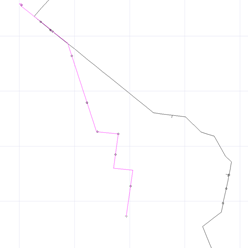
Figure: CDEGS Pipeine LFI Model
Magnetic Fields
The long term health effects of magnetic fields on humans are not well known, and there doesn’t seem to be any firm consensus regarding the dangers, if any, long term exposure to magnetic and electric fields may pose to human health. The International Commission on Non-ionizing Radiation (ICNIRP) has some guidelines, but there are no standards currently in Australia regarding acceptable values. If there are concerns, a number of software programs exist to calculate the magnetic and electric fields. Zero Sequence use CDEGS Hifreq module to calculate the Electric and Magnetic fields near HV feeders.
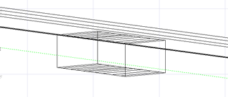
Figure: CDEGS Building next to HV line for Electric an Magnetic Field Calculation
Zero Sequence Earthing would be happy to help with any questions or problems you may have with third party interference assessments.
Zero Sequence Earthing
(02) 4039 8000 / 0434 190 272