For a general description and introduction to grounding, read the Introduction To Grounding article on this site.
This guide to Grounding System Testing is intended to help address the following:
- How to test an electrical grounding system
- What test method is best
Testing Options
This article will briefly discuss the following test methods commonly associated with assessing electrical grounding systems:
- Soil Resistivity testing (wenner method)
- Continuity testing
- 3 point resistance measurements
- Current injection testing
Visual inspection, loop impedance testing and impulse testing are not covered in this article.
Soil Resistivity Testing
Soil resistivity plays a large part in earthing systems:
- Directly affect the ground resistance
- Affect the voltage safety targets
- Affect the voltages on the soil
There are a few methods for assessing soil resistivity. The Wenner method is typically used for grounding applications: a current is passed through two earth stakes, and a voltage is measured on the other two.
Accurate soil data is needed for surface layering and safety criteria calculation, and deeper (longer traverses) are required for an understanding of voltage over the soil and the performance of the grounding system. It’s important that traverses are conducted to spacings far enough apart to give an understanding of the deeper layering, this may mean moving some distance from the site to get more space.
Buried metallic objects will cause the current to flow through them preferentially (a short circuit) so care must be taken to minimise interference.
Soil resistivity is not typically homogenous, it is often geologically in horizontal layers.
For an optimal ground grid design, the earth grid conductors/electrodes are most effective in the lower layer soil resistivity. In general:
- If the soil is low on high – more horizontal buried ground grid
- If the soil is high on low – preference towards deeper ground rods
Continuity Testing
Continuity testing is used to measure how well two items are connected together.
The basic principle is that a fixed current (1Amp DC) is passed through a circuit consisting of the items you are measuring (connected by a buried earth grid) and the voltage rise is measured. Based on Ohms law, the resistance between the two points is proportional to the current and the voltage, hence (not forgetting the circuit impedance itself) it’s a measure of how well connected items are.
Best practice in continuity testing is to use a 4 wire system, with one pair passing current and the other simply measuring voltage, thereby eliminating the resistance of the cables themselves.
3 Point Resistance Testing
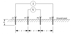
Also called the 4 point resistance method, or the Fall Of Potential (FOP) method, this test has the benefit of being fast and simple in providing an apparent grid resistance, however its capabilities are limited to smaller isolated ground grids, as it is not able to provide information on the current paths of interconnected systems, or transfer, touch and step voltages. Any Ground Potential Rise (GPR) from this system is implied from the apparent grid resistance measured.
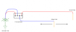
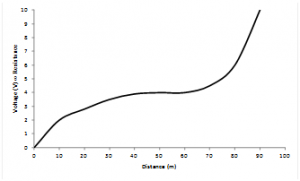
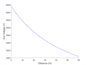
In this test, a current is passed through a circuit consisting of the grid under test and a temporary ground grid (the current stake below), and a voltage is measured using the voltage probe from the ground grid under test to the soil between it and the current stake, to produce the curve given below.
The point of inflexion in this curve gives the resistance of the ground grid. The current stake needs to be sufficiently far away to give a flat spot in this curve, and this distance is influenced by the soil layering and magnitude.
If there are any other current paths, or the grid under test is a very low resistance, or you are unable to place the current stake far enough to get a curve, then current injection testing will be required.
Current Injection Testing
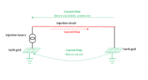
Current injection testing is used to simulate a single phase to ground fault by injecting a low power, off frequency current into the grounding system. Provided the injection circuit used is the same or similar to the actual fault circuit, it enables real world voltages and currents to be measured, albeit at scaled down magnitudes.
In order to ensure the simulated voltages and current are directly comparable with the fault scenario under consideration, the circuit used to inject current must closely match the fault circuit, or that any sources of error are known and can be quantified. Ideally, the actually fault circuit should be used – this typically means injecting current over an out of service feeder between the fault location and the supplying substation. If this is not possible, a temporary circuit consisting of a “feeder” simulated by a temporary cable and supplying substation consisting of a temporary grid, can be used, but care must be taken to understand sources of error and correct for them if required.
Ground Potential Rise (GPR) Measurement
The ground potential rise is measured by taking voltage measurements between the ground grid under test and the soil in increasing distances from the ground grid.
Current Distribution Measurements
The current is measured in auxiliary current paths such as cables screens and overhead ground wires to evaluable the performance of those paths, and in order to calculate the local grid resistance of the ground grid.
Touch, step and transfer voltages
Measurements are taken with a high impedance frequency tunable meter to determine the voltage hazards close to and transferred from the earth grid under fault.
Summary – When to Use What
Soil Resistivity testing critical to design – always test soil resistivity for Greenfield sites and for brownfield sites if you are doing design work.
Continuity testing – Do this as part of routine maintenance for existing ground grids. It is a simple method for identifying degrading joints and connections over time. In most cases, the same equipment used for soil resistivity testing can be used for continuity measurements.
3 Point resistance testing – A simple and straightforward test for giving ground mat resistances if the limitations are obeyed. The same equipment used for soil resistivity and continuity can be used for this testing. If the following conditions cannot be readily satisfied, use the current injection testing method:
- Ground grid / ground mat is standalone (not external grounding connections such as LV neutrals, overhead ground wires, cables screens, or long counterpoise conductors non-negligible reactive impedances)
- The ground grid is not a very low resistance
- The current stake can be sufficiently far enough to find the flat point of the curve
- Compliance is related to grid resistance more than voltage limits (such as for lightning protection grids)
Current injection testing – This is the most powerful and most accurate if used correctly (an understanding of the circuit and sources of error is essential).
The current injection testing method:
- Most accurately represents the ground grid under fault conditions
- Can directly measure current in connected earthing paths
- Directly measure Ground Potential Rise, and associated voltage hazards (i.e touch, step and transfer)
Zero Sequence Earthing is happy to provide advice on which method is best for you installation given your goals for the assessment.
4 thoughts on “Electrical Earthing System Testing – Application Guide”