
This article is intended to provide a brief overview and of earthing in underground coal mines, and the practicalities and requirement of separation.
For a general description and introduction to earthing, read the Introduction To Electrical Earthing article.
For a guide to applying the most appropriate testing methodology to assess your earthing system read the Application Guide to Earthing System Testing.
For a guide to current injection testing, read our article Earthing Assessment using Current Injection Testing.
An earthing system is any system intended to carry fault current back to the source, and commonly consists of electrodes and buried grid in contact with the soil, and also includes overhead earth wires, cables screens, connected metallic objects, and the soil itself.
Earthing on Mine Sites
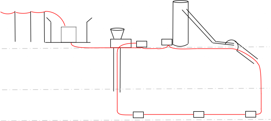
Earthing on a mine site can be broadly broken into three areas described below and in Figure 1.
- Network earth – this is the earthing system of the supplying utility network (including overhead earth wires) and may include the main HV substation earth grid.
- Surface earth – this is the earthing system associated with HV, MV and LV cable screens across the surface plant, motors, structures and all metalwork across the site.
- Underground earth – this is the earthing associated with the underground workings, electrical reticulation, services and metalwork underground.
Standards and Guidelines
Australian standards AS3007, AS1768, AS2067 and the NSW Department of Industry requires that the surface and underground earthing systems minimise or prevent the transfer of electrical energy for surface faults and lightning strikes from transferring to underground workings where potentially hazardous atmospheres may exist. In effect this generally means separation of surface and underground earths, and fault limitation for underground workings. Fault limitation of underground supplies is a requirement of the standards.
Unlike surface and underground systems, separation of network and surface earthing systems is not essential and will depend on site specific considerations.
Earthing Hazards on Site
Considering the mine site earthing as three areas as above, Network, Surface and Underground, is a good way to think about fault scenarios that can occur on the site.
Network
- Faults may occur elsewhere on the network and transfer to the site via the overhead earth wire (OHEW) if one exists.
- A primary HV fault may occur at the main substation, which can then be transferred to the surface or underground earthing systems.
- A secondary fault may occur on the surface of the mine (which also produces an Earth Potential Rise, EPR, at the main substation), and this too can be transferred along other connected cable screens.
Consideration of whether to connect or separate the main substation to the network’s earth, and whether to connect the main substation to the surface earth will depend on factors such as fault level and clearing time, proximity to mine infrastructure, and the utility connection arrangement such as the presence of OHEWs or fault limitation on the incoming supply.
Zero Sequence Earthing suggest that if it is safe to do so and the existing surge protection and lightning scheme allows for, the preference would be to connect the network earth, main substation and surface earth together, as the positives (current return paths, lower system impedance) often outweigh the negatives (voltage transfer hazards) in such an arrangement, however it is a site-specific decision.
Surface
- Faults at surface substations may produce high voltage hazards on interconnected plant.
- Surface faults may transfer to underground locations if they are not separated or the separation is inadvertently bridged.
- Lightning strikes to or near surface plant may transfer to other locations such as underground working if they are not separated, if the separation is insufficient or inadvertently bridging has occurred.
- An insulation coordination study to size, locate and verify the suitability of surge arrestors and lightning protection is also highly valuable in minimising the risk of transferring lightning energy to underground workings.
The surface earthing arrangement depends on site layout and substation locations, how the substations are supplied the fault levels and clearing times. Given the underground earthing is often separated from the surface, it is often standard practice to include fault limitation on the surface as well as underground feeders by using a Neutral Earthing Resistor (NER) on the neutrals of the supplying transformers. This is especially helpful if there are any distant substations supplied by overhead feeder (such as remote vent fans or bore pumps etc) where compliance for the full fault level may be difficult.
Underground
- Faults underground need to return to the supplying substation located on the surface. Without a dedicated return path and generally high local earth resistances, high voltage hazards can occur if the fault level is high.
- A fault limited supply is essential to underground areas that have separated earthing systems from the surface. Underground coal seams generally produce high resistance earth grids; coal and rock are high resistivity mediums, and substations are often transportable and do not have large earthing systems associated with them. The presence of a large network of roof mesh, rock bolts and shotcrete containing metal can produce a low earthing system impedance underground, however not every mine has this arrangement.
If an inherent underground earth grid such as that described above with roof mesh is not available, one will need to be installed either in the underground workings (i.e inside the portal) or on the surface close to the portal. If installed on the surface, care must be taken to isolate it from the surface earth and lightning strikes.
Zero Sequence Earthing suggest that the following would be the ideal underground earthing arrangement, however the final solution and implementation is site specific.
- Separate surface and underground services such as pipes, conveyors, and HV cables screens at the portal by creating a joint at the portal and cutting the screens, bonding the UG side to the UG earth grid, or isolating it entirely, and bonding the surface side back to the surface earth grid.
- At boreholes and vent fans it can be difficult to create a break at the transition, leaving part of the underground earth exposed to the surface. For boreholes, Zero Sequence suggest that a separation point is created at the top and bottom of the borehole, decreasing the changes of an inadvertent bridge of the surface and underground earthing systems.
- For the underground earth grid, usage of the bonded roof bolts and mesh/shotcrete works well, but if this is not available a dedicated earth grid consisting of electrodes and conductors may be required inside the portal.
- All surface services and metal work are part of the surface earthing system and the separation happens at the transition to underground. In this arrangement, the delineation between surface and underground earthing systems is clear and less likely to be mistaken. In practice, implementation will depend on existing practises and local site conditions.
Generally, if there is an existing separation and bonding philosophy employed on site, it is generally not practical to change this in favour of another unless necessary. There may be several ways to limit voltage transfer within the site constraints.
Zero Sequence Earthing are happy to provide advice and assistance with carrying out earthing system assessment, including site testing such as current injection testing, soil resistivity or three-point resistance (FOP), and design work using CDEGS.