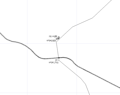
Background and methodology
Electrical Hazards to Pipelines
Wherever a pipeline is close to or running parallel to a HV line there exists a potential for electrical hazards on the pipeline. Current industry trends including the Australian Standard ‘AS4853 electrical hazards on metallic pipelines’ take a risk assessment based approach to hazard identification and management.
Hazards to pipelines from nearby HV lines can include:
- Earth Potential Rise (EPR) from faults at nearby assets transferring voltage to nearby pipeline appurtenances through the soil
- Low frequency induction (LFI) creating voltage on the pipeline due to faults over a parallel conductor
- Capacitive coupling causing voltage on an unearthed pipeline subject to an electric field beneath a high voltage line. This is largely negligible to buried pipelines.
Steady state corrosion effects are largely not applicable to a hazard assessment as they result in relatively low magnitude voltages when compared with LFI due to power system faults.
Hazard Assessment Levels
AS4853 allows for a stepped risk assessment, starting with a conservative first-pass assessment and working up to detailed assessment.
Level 1 hazard assessment
This is a conservative first pass assessment of the pipeline separation and exposure length against pre-defined tables for acceptance.
Level 2 hazard assessment
This is a conservative assessment of calculated voltages on the pipeline (these can be detailed or conservative calculated values) against pre-defined safety limits based on typical conservative inputs such as fault rates and contact scenarios.
Level 3 hazard assessment
This is an assessment of the voltage produced on the pipeline (this can be a simple/conservative calculation or a detailed model) against calculated safety criteria applicable to the fault and contact scenario. This generally requires more inputs and is typically more detailed and less conservative.
An alternative to a detailed calculation is to conduct a current injection test to simulate a fault and measure the voltage produced to the pipeline. This has some benefits in that it can be cheaper and simpler while producing more accurate results, provided the actual fault scenario can be accurately replicated.
Input information required to conduct assessment
Level 1 input information required
- Pipeline route
- Type of pipeline
- Powerline route
- Soil resistivity and fault level are helpful if already available, but not absolutely required
Level 2 input information required
- Soil resistivity
- Detailed powerline and pipeline routes (and separation distances)
- Powerline details (voltage, OHEW, conductors, construction/heights, tower/pole earthing details)
- Single line to ground fault levels, X/R ratios and clearing times
- Load currents (for steady state LFI calculations)
- Pipeline details (material, size, coating type and thickness, coating condition (if known), burial depth, insulating joints, location of valves and appurtenances, CP points, earthed points or anode beds, installed surge protection, offtakes)
Level 3 input information required
- Data for level 2, plus;
- Line fault rates and contact frequency and duration at appurtenances/CP test points – if this data is not available then reasonable values will be chosen from AS4853 as suited to the line type and pipeline type
